This is an old old old archive. Please don't trust any information you find on this wiki. Looking for up-to-date information? Go to hsbxl.be or join our Matrix channel.
Workshop NE-555 Chip
|
Who is interested in doing his first steps in this "all you can eat" IC (integrated circuit) NE555 (or cheaper equivalent)?
we ll have a look on theory , we ll learn to do the math , and then let s go for practice , proto , soldering etc...
learn and proto circuit on demand : ex flashing led , function generator , sound generator , servo-motor control , and much more (like thousand of possible applications )
Date[edit]
Saturday 20th november
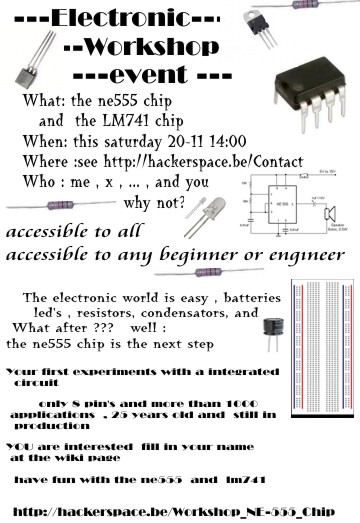
Flyer[edit]
Needs[edit]
if you have , bring every electronic you can ex : proto-boards , soldering iron , ... if we know how many people s gonna attend , we ll supply the NE555 (or equivalent) and basics (res ,condos...) we ll also use the java simulator , so if you wana bring your computer ...
Who[edit]
- Pastec
- LineKernel
- ptr_
- zoobab
- Jobj
- Arak
Links[edit]
Notes[edit]
555 workshop http://www.falstad.com/circuit/ pastech docs
http://www.talkingelectronics.com/projects/555/Page1-555.html
Schematics : http://en.wikipedia.org/wiki/File:NE555_Bloc_Diagram.svg
- bad for use with batteries / 555 (consumes power in small pulses - so it can perturbate the power line/noise)
- crow-bar ? we'll see later
- oscillator? 555 is making too noisy signals to call it an oscillator probably
- (XR2206 better for oscillating purposes)
- it's a 'timer',it needs 3 external components to make an oscillator (1Hz to 500Hz)
- 28 transistors grouped
1Hz to 500kHz (freq lower then 1 Hz: we call it 'delay' -- but 555 is not really reliable in this
- mark-space : when signal is low (cfr morse-code)
- Rail : distributed power to other components (the farthest, the noisier)
Each pin has a function, if you don't use it, put it down.
pin 2 - prevent the timer from starting until LOW : 'trigger': / is connected to the condensator, detects his power (up or down) pin 4 - stops oscillating : 'reset' pin 5 - ratio: duty-cycle of the oscillation pin 1 - GROUND (not minus!) pin 3 - Output pin 8 - Vcc pin 6 - THRESHOLD pin 7 - DISCHARGE (cfr the condensator/capacity that controls timing)
! check if a 555 is burnt : measure resitance betwin pin 8 and 1 and get 15kohm
pin2: 'trigger' measures the voltage on the capacitor C ( checks if the voltage on the capacitor is lower then 2/3rds of the supply power
ping 6: 'threshold'
pin 7 : 'discharge' whenever 'control flip-flop' triggers it puts pin7 to ground
pin 3: totem-pole : idem as soviet-tank output : can sink 200mA -- drive speaker, small light bulb,...
+- 1.7 volt loss
sink : drive power - between the pin and ground
High state voltage = 13.3 volts (non complete)
slew-rate = rise/ fall-time (here we have 100ns)
the first state of the system is HIGH then the capacitor charges (2/3) , then flop to discharging state
pin 5 - you can apply a voltage to play with the frequency
NPN
(negative - positive - negative)
(base is in the middle - needs positive voltage to flow current)
PNP (put base on ground to make it conduct)
pin names with a line above: means pin is ACTIVE LOW.

